
 English
 中文简体
中文简体 русский
 Español
 عربى
عربى
Don't hesitate to contact when you need us!
 Home / News / Industry News / CNC Coding Language Explained: G-Code, M-Code, and Control Dialects for Machinists
 CNC Coding Language Explained: G-Code, M-Code, and Control Dialects for Machinists
 2026.10.14
 Industry News
Two lathes standing side by side in the same workshop can run what looks like the same program and still behave differently. One control reads G71 as a two-block turning cycle and roughs the part exactly as written; another expects a cycle call and alarms out on the first line. That gap is why the phrase CNC coding language deserves a real definition instead of a one-word answer.
The short answer: the CNC coding language is G-code, standardized as ISO 6983, built from address letters that describe motion, feed, speed and tool selection. Around that core, each control builder layers its own M-codes, canned cycles, macro variables and synchronization commands. Learn the standard core and you can read almost any program. Learn the dialect and you can actually run the machine.
What follows covers block structure, the codes used every day, modal groups and the ordering traps inside them, the main dialect families, macro and sub-spindle programming, and how to prove a program out before it touches metal.
Content
- 1 What the CNC Coding Language Actually Consists Of
- 2 Anatomy of a Single Block
- 3 The G-Codes You Will Meet Every Day
- 4 Modal Groups and the Ordering Traps Inside Them
- 5 Dialects: Why the Same Job Needs Different Code
- 6 Macros, Subprograms and Sub-Spindle Work
- 7 How to Prove Out a Program Before It Cuts Metal
- 8 What to Ask Before You Buy a Machine
What the CNC Coding Language Actually Consists Of
G-code carries geometry and feed: where the tool travels, how fast, and along which path. M-codes carry machine functions: spindle on and off, coolant, chuck clamp and unclamp, tool change, tailstock, program stop. Address letters supply the parameters - X, Y and Z for position, F for feed, S for speed, T for tool and offset, N for sequence number.
Three details catch people out early. On most turning centers, X is programmed as a diameter rather than a radius, so X50.0 turns a 50 mm diameter. Feed can be per minute (G98) or per revolution (G99), and the same F value means something entirely different under each mode. And G-code is not a single file format: a control reads one specific dialect, and a CAM post-processor has to be written for that dialect before the output will run.
If you are still building fluency, a plain-language overview of turning and milling fundamentals is worth an hour of your time before you start editing production programs.
Anatomy of a Single Block
A block is one line of a program, and it only needs the addresses that change. A roughing move on a lathe might read N120 G01 X48.0 Z-32.0 F0.25 - a sequence number, a linear interpolation command, an absolute diameter position, an absolute Z position, and a feed of 0.25 mm per revolution.
Read left to right, the block is a sentence: the machine is told what kind of move to make, where to end up, and how fast to get there. The letters that appear are the vocabulary of the language.
| Address | What it does | Example |
|---|---|---|
| N | Sequence number for the block; useful when searching or restarting mid-program | N120 |
| G | Preparatory or motion command | G01 |
| X, Y, Z | Target position on the main axes; absolute under G90, incremental under G91 | Z-32.0 |
| U, W | Incremental travel on many turning controls, with U usually written as a diameter | U0.5 |
| F | Feed rate; per minute under G98, per revolution under G99 | F0.25 |
| S | Spindle speed in rpm, or surface speed when constant surface speed is active | S800 |
| T | Tool number and offset number, often written together | T0303 |
| M | Machine function such as spindle direction, coolant or program stop | M08 |
| R, P, Q, D | Cycle and compensation parameters; the meaning depends on the cycle in use | P100 Q200 |
| # | Macro variable used for arithmetic and for passed values | #100=25.0 |
The table is vocabulary; the grammar is modal state. A control remembers what was active on the previous line and keeps applying it until another command from the same group replaces it.
The G-Codes You Will Meet Every Day
A working turning program uses a surprisingly small set of G-codes. The table below covers most of what appears on a two-axis lathe in an ordinary week.
| Code | Function | Typical use |
|---|---|---|
| G00 | Rapid positioning, non-cutting | Approach and retract moves |
| G01 | Linear interpolation at a set feed | Turning, facing, boring |
| G02 / G03 | Circular interpolation, clockwise and counter-clockwise | Radii, fillets, spherical forms |
| G04 | Dwell for a set time | Bottom of a blind bore, groove cleanup |
| G20 / G21 | Inch and metric input | Set once at the top of the program |
| G28 | Return to machine reference position | Safe start and end of program |
| G40 / G41 / G42 | Cutter compensation cancel, left and right | Milling profiles and edges |
| G43 | Tool length compensation | Tool changes on a machining center |
| G50 / G92 | Spindle speed clamp or coordinate setting, depending on the control | Speed limits and simple setups |
| G54 to G59 | Work coordinate systems | Multiple fixtures on one table |
| G70 / G71 | Finishing and roughing cycles for turning | Stock removal on a lathe |
| G76 | Threading cycle | Single-point internal and external threads |
| G81 / G83 | Drilling and peck drilling cycles | Hole patterns, deep holes |
| G84 | Tapping cycle | Synchronized tapping |
| G96 / G97 | Constant surface speed on and off | Facing and turning at a fixed surface speed |
| G98 / G99 | Feed per minute and feed per revolution | Deciding how F is interpreted |
On a two-axis lathe the list shrinks further. Roughing, finishing, threading, drilling and constant surface speed cover the great majority of production work, which is why turning programs tend to look compact until a live tool or a second spindle enters the picture. A machine such as the CK6150 high-power horizontal lathe is programmed almost entirely with G71, G70 and G76, with G96 handling surface speed while facing.
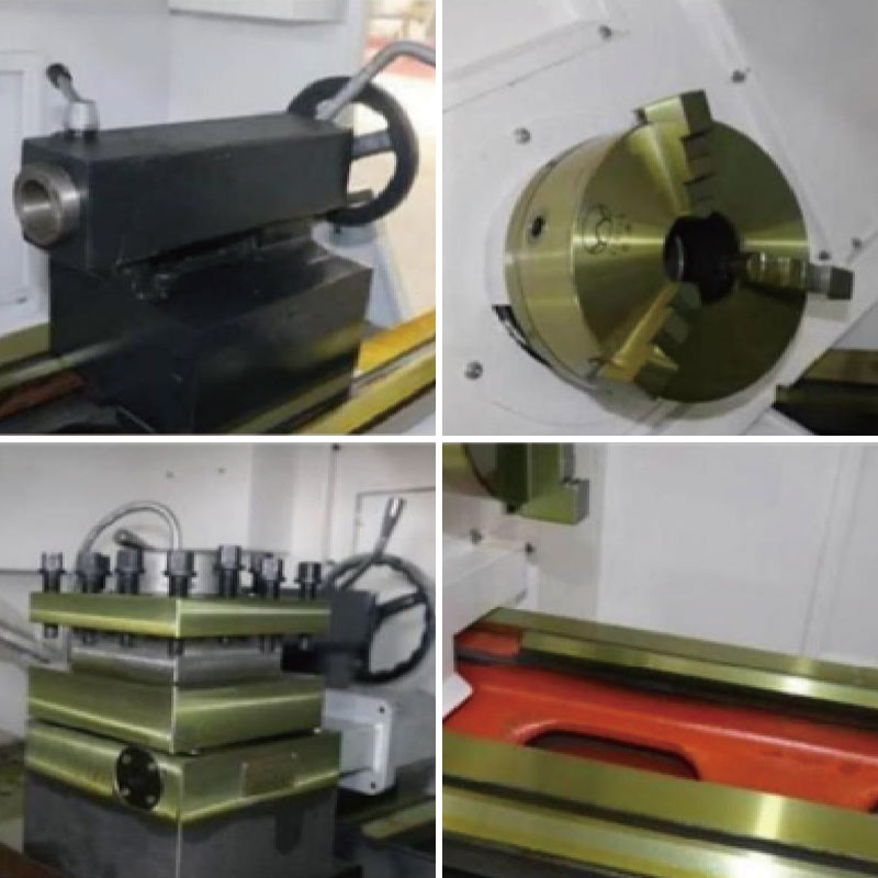 CK6150 high-power CNC horizontal latheNumerical control latheView Product →
Modal Groups and the Ordering Traps Inside Them
Every G-code belongs to a modal group, and only one code from a group can be active at a time. G00, G01, G02 and G03 sit in the same group, so writing G01 cancels the rapid move that was active before it. You never need to switch a modal command off; you simply issue the next command from the same group when the move type changes.
A handful of codes are non-modal and act only on the block where they appear. G04 dwell, G28 reference return and G53 machine-coordinate moves are the usual examples.
Ordering inside a block matters just as much. Four habits prevent most surprises:
- Put the unit command (G20 or G21) before any coordinate, and never in the middle of an active cycle.
- Set the feed mode (G98 or G99) before the first F value. Switching from per revolution to per minute with the same F number can change the actual feed rate by a factor of more than a hundred.
- Place a tool call and its offset on the line before the move that uses it, not after.
- Retract with G00 to a safe position before cancelling cutter compensation or a canned cycle.
These are not stylistic preferences. They decide whether the next block is a rapid into the workpiece or a controlled feed at cutting depth.
Dialects: Why the Same Job Needs Different Code
The standard defines the core of the language, not all of it. Threading, drilling cycles, tool management and macro syntax are left to the control builder, so a program written for one control family generally needs editing before it will run on another.
Two families appear most often on general-purpose lathes and turning centers: the Fanuc-style multi-block cycles and the Siemens-style cycle calls. In day-to-day programming the differences look like this.
| Function | Fanuc-style control | Siemens-style control |
|---|---|---|
| Threading | G76 with two or more parameter blocks | G33 or a dedicated threading cycle call |
| Drilling cycles | G81, G83 with R and Q parameters | Cycle calls with depth, dwell and retract parameters |
| Tool radius compensation | G41 and G42 with a D offset number | G41 and G42 with the radius taken from the tool table |
| Subprogram call | M98 with a program number | A subprogram name or an explicit call statement |
| Macro variables | Numbered variables written with # | R-parameters |
| Constant surface speed | G96 with a separate speed clamp | G96 with an upper limit parameter |
Here is the practical consequence for a buyer: the dialect is decided at purchase, not on the shop floor afterwards. If a lathe is specified with a Siemens 808D control, then the programs, the post-processor and the operator training all have to match that choice. A machine like the CK5116B single-column vertical lathe, which is supplied with the Siemens 808D system, will not accept a Fanuc-style cycle file without the cycle blocks being rewritten.
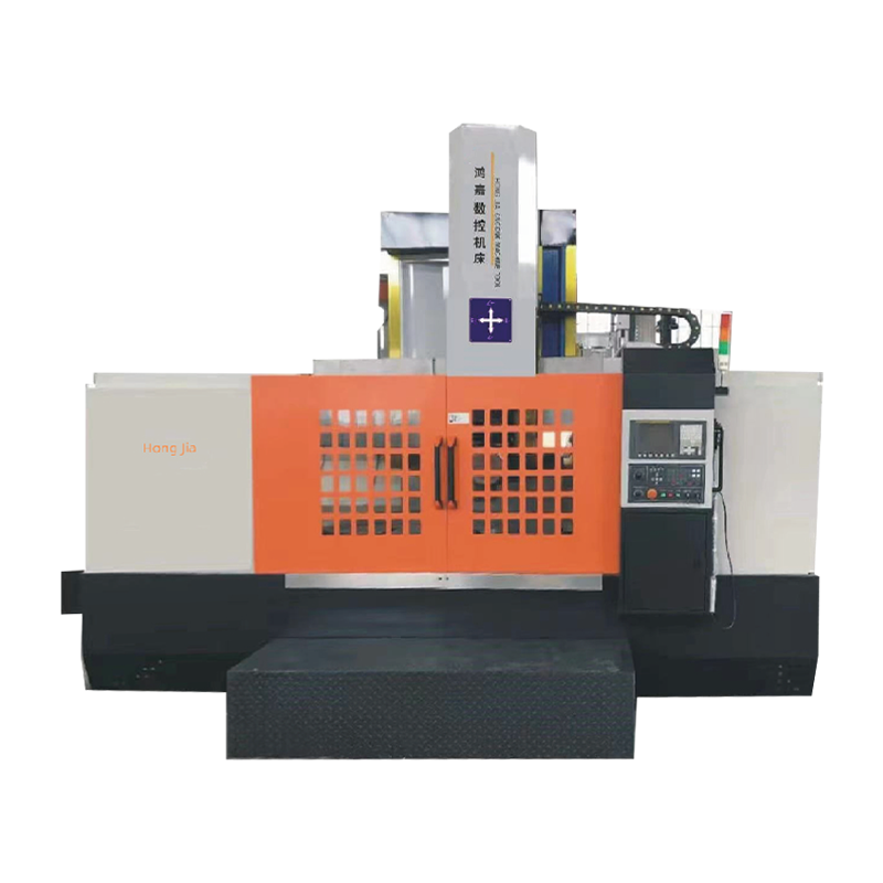 CK-5116B Siemens 808D CNC single-column vertical latheNumerical control latheView Product →
Macros, Subprograms and Sub-Spindle Work
Once a part family shares a shape and differs only in dimensions, hand-editing each program stops making sense. Two features remove most of that work, and a third changes how the whole sequence is planned.
Subprograms
A subprogram holds a repeated sequence - a groove profile, a hole pattern, a deburring pass - and is called from the main program. Change the subprogram once and every calling program picks up the change at the next run.
Macro variables and loops
Macro variables store numbers that the program can calculate with. A single macro can bore a family of diameters, stepping a variable between passes and stopping on a condition, instead of duplicating the same cycle for every size. Because the arithmetic syntax is dialect-specific, macro-heavy programs are the least portable part of any program library.
Two spindles, two channels
On a dual-spindle turning center the program also has to coordinate two spindles: cut on the main spindle, part off, hand the blank to the sub-spindle, finish the second face. Synchronization codes and wait commands keep both sides from colliding, and this is the least standardized area of the language. It is exactly the territory covered by machines such as the NC106DS dual-spindle automatic docking turning center, where the transfer sequence is built into the machine design rather than improvised in the program.
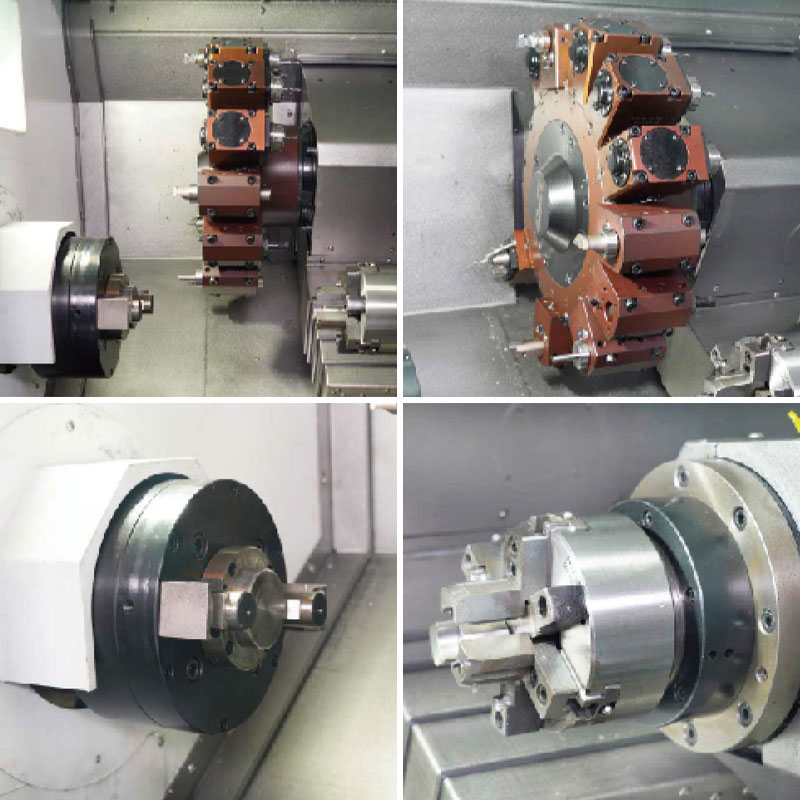 NC-106DS dual-spindle automatic docking horizontal turning centerThe dual-spindle automatic docking horizontal turning center is an advanced machine tool that integrates multiple processing functions such as turning, drilling, borin...View Product →
How to Prove Out a Program Before It Cuts Metal
Almost every crash has the same shape: the code was never verified against the machine's actual state. A short routine catches nearly all of them.
- Simulate on the control or in CAM and check the toolpath against the drawing, not only for collisions.
- Run the program with rapid override reduced and single block active, watching the distance-to-go display on every approach.
- Shift Z positive by a safe amount and run the whole program in the air, confirming tool changes, offsets, spindle direction and coolant.
- Cut the first part with feed override reduced, then check every dimension against the drawing before releasing the program to production.
- Record the offsets, the program version and the tool list on a setup sheet so the next run starts from known values instead of memory.
Two minutes of single-block work at the machine costs far less than a broken tool holder or a scrapped batch.
What to Ask Before You Buy a Machine
Because the coding language is tied to the control, machine selection and programming practice are the same decision. Before signing, it is worth confirming a few points in writing:
- Which control is fitted, and which dialect that means for cycles, macros and subprograms.
- Whether a post-processor for your CAM system already exists for that control.
- How much program memory the control has, and whether drip feeding is needed for large surfacing files.
- How many work offsets and tool offsets are available for multi-fixture setups.
- Whether sample programs, a parameter backup and operator training are included.
- What the stated acceptance standard is, and whether the test cut runs on your part or a demonstration part.
A builder that has spent two decades on metal-cutting equipment and ships around a thousand units a year tends to have settled answers to these questions. You can read more about the background and history of the team behind these lathes before you shortlist a model.
