
 English
 中文简体
中文简体 русский
 Español
 عربى
عربى
Don't hesitate to contact when you need us!
Parts of a CNC Milling Machine Explained: Function, Specs & Tips
 2026.09.02
 Industry News
Content
- 1 Core Answer: The Essential Parts of a CNC Milling Machine at a Glance
- 2 Structural Components: Bed, Column and Worktable Compared
- 3 How the Machining Process Flows Through Each Part
- 4 Key Spindle and Motor Specifications That Affect Performance
- 5 Choosing the Right Tool Holder and Automatic Tool Changer
- 6 CNC Milling Machine Parts vs CNC Lathe Parts: Common Mix-Ups
- 7 Maintenance Checklist for Long-Term Part Reliability
- 8 Safety Notes When Handling Moving Parts
- 9 Frequently Asked Questions About CNC Milling Machine Parts
Core Answer: The Essential Parts of a CNC Milling Machine at a Glance
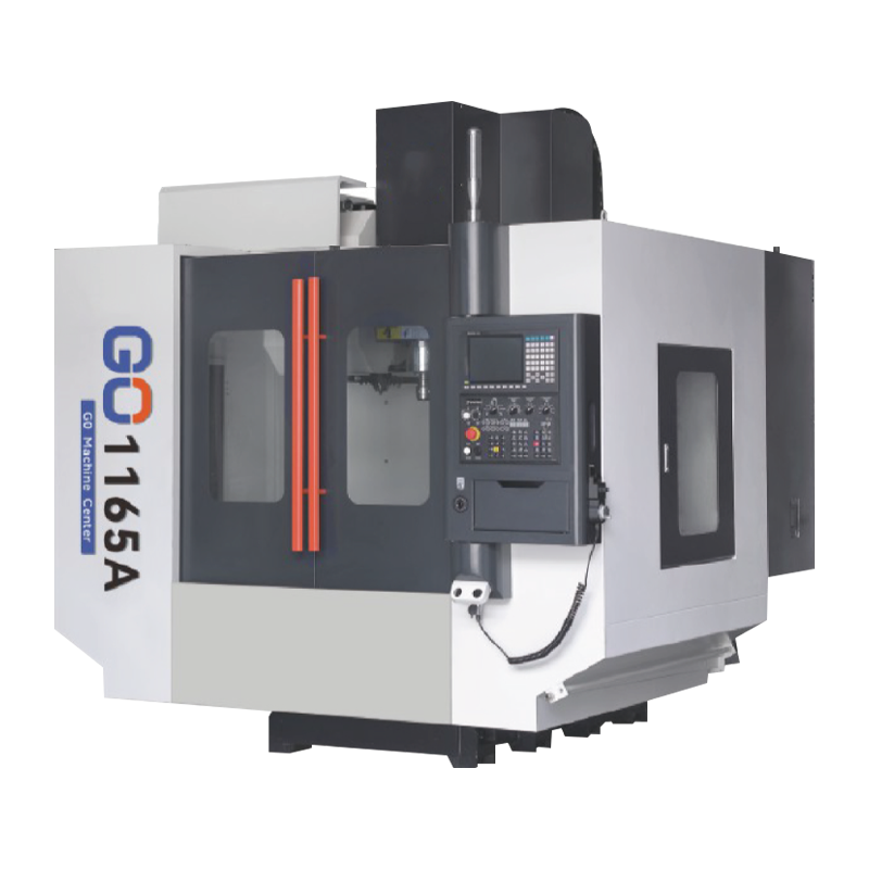
A CNC milling machine is built from seven core groups of parts: the machine base and column, the worktable, the spindle unit, the axis drive system (servo motors, ballscrews and linear guideways), the tool magazine with its automatic tool changer, the CNC controller, and the coolant and lubrication system. Every one of these groups has a direct, measurable effect on cutting accuracy, rigidity and daily output, so understanding what each part does is the fastest way to evaluate, operate or maintain a milling machine correctly.
A typical 3-axis vertical machining center runs a spindle speed range of 6,000 to 12,000 RPM, a worktable travel of roughly 800 to 1,000 mm on the X-axis, and rapid traverse rates between 24 and 48 m/min. The sections below break each part down individually, explain how they interact during a machining cycle, and show where milling machine parts differ from CNC lathe parts so buyers do not confuse the two machine types.
How the Machining Process Flows Through Each Part
Understanding parts in isolation is useful, but seeing how they cooperate during a single machining cycle makes the relationship between them much clearer.
- 1Clamping — the workpiece is fixed onto the worktable through a vise, fixture or clamping plate.
- 2Tool loading — the automatic tool changer pulls the required cutter from the tool magazine into the spindle.
- 3Positioning — servo motors drive the ballscrews, moving the table and spindle head along programmed X, Y and Z coordinates.
- 4Cutting — the spindle rotates the tool at the programmed RPM while coolant is sprayed onto the cutting zone.
- 5Finishing — once all toolpaths finish, the table returns home and the finished part is removed for inspection.
Key Spindle and Motor Specifications That Affect Performance
A 15 kW spindle motor can cut roughly three times faster in steel than a 5.5 kW unit under the same tool diameter.
The spindle and its drive motor are usually the single most expensive part group on a CNC milling machine, and their specification decides what materials and cutting depths the machine can handle. Common reference ranges include:
- Spindle power: 5.5 kW to 15 kW for general-purpose vertical machining centers
- Spindle speed: up to 12,000 RPM on standard models, with high-speed spindles reaching 24,000 RPM
- Rapid traverse: 24 to 48 m/min depending on servo motor torque and ballscrew lead
- Positioning accuracy: typically within ±0.005 mm on a well-maintained axis system
Choosing the Right Tool Holder and Automatic Tool Changer
The tool holder and the automatic tool changer (ATC) work together to swap cutters mid-program without manual intervention. Getting this part group right has a large impact on cycle time and repeatability.
Practical selection tips
- Match the tool holder taper (BT30, BT40, or HSK) to the spindle nose specification before ordering tooling.
- Check ATC capacity — a 16 to 24 station magazine covers most general milling jobs without frequent manual reloads.
- Verify tool change time, since a fast changer averaging 1 to 2 seconds per swap can shave meaningful minutes off a multi-tool program.
- Balance tool holders above roughly 8,000 RPM to prevent spindle bearing wear from imbalance vibration.
CNC Milling Machine Parts vs CNC Lathe Parts: Common Mix-Ups
Buyers new to CNC equipment often assume a CNC lathe and a CNC milling machine share the same part names, but several components serve very different roles on each platform. The table below clears up the most frequent confusion.
| Part | On a CNC Milling Machine | On a CNC Lathe |
|---|---|---|
| Workholding | Vise or fixture bolted to a stationary worktable | Chuck that rotates the workpiece against a fixed tool |
| Spindle role | Spins the cutting tool while the workpiece stays still | Spins the workpiece while the cutting tool stays still |
| Axis layout | Usually X, Y and Z linear axes | Usually X and Z linear axes with continuous C-axis rotation |
| Best-fit parts | Pockets, slots, flat faces, drilled patterns | Round shafts, sleeves, threaded and tapered parts |
Key part-level differences between a CNC milling machine and a CNC lathe.
Maintenance Checklist for Long-Term Part Reliability
Most part failures on a CNC milling machine trace back to skipped lubrication or delayed cleaning rather than defective components. A simple, consistent checklist extends part life significantly.
- Lubricate ballscrews and linear guideways on the schedule set by the manufacturer, commonly every 40 to 80 operating hours.
- Inspect the ATC gripper arm and tool clamping mechanism monthly for wear that could drop a tool mid-cycle.
- Clean coolant filters and check concentration weekly to prevent nozzle clogging and spindle overheating.
- Check spindle bearing temperature during warm-up; a stable reading under 60°C after 20 minutes generally indicates healthy bearings.
Safety Notes When Handling Moving Parts
Several parts on a CNC milling machine move at high speed or carry stored energy, so a few safety habits should never be skipped.
- Keep the spindle guard and axis covers closed during any cutting cycle; never reach into the work zone while the spindle is rotating.
- Lock out the machine power before servicing the ATC magazine, ballscrews or coolant pump.
- Use the correct tool holder balance grade at high RPM to avoid sudden tool ejection.
- Wear cut-resistant gloves only when the spindle is fully stopped, never while it is turning.
Frequently Asked Questions About CNC Milling Machine Parts
QWhich part wears out fastest on a CNC milling machine?
Cutting tools and tool holders wear out first because they are in direct contact with the workpiece, followed by ballscrews and linear guideways if lubrication is neglected.
QCan the same tooling be used on a CNC milling machine and a CNC lathe?
No. A CNC lathe uses turning inserts and single-point cutting tools mounted in a fixed tool post, while a milling machine uses rotating end mills, drills and face mills held in the spindle.
QHow often should the CNC controller and drive parts be checked?
A basic inspection of connectors, cooling fans and backup batteries every three to six months is usually enough to prevent unplanned electrical downtime.
QWhere can I see complete part configurations for a CNC milling machine?
Full spindle, axis and tool magazine specifications for current models are listed on the Hongjia CNC product page.
