 English
 中文简体
中文简体 русский
 Español
 عربى
عربى


A lathe spins the workpiece while the cutting tool advances into it. A milling machine does the opposite: the cutter rotates while the workpiece stays clamped on the table. That single kinematic difference drives nearly every other contrast between the two machine types — the shapes they produce, the operations they perform, the workholding they require, and the way production is planned around them.
If you are buying CNC equipment for a machine shop or a production department, this distinction should be your starting point. Choose the correct machine principle and the rest — spindle speed, axis travel, tooling, automation options — falls into place around the parts you make. Choose incorrectly and the machine will struggle with your parts, no matter how advanced its control system is.
This guide explains the difference between a mill and a lathe from a practical shop-floor perspective, including key comparisons, typical applications, and the selection logic that equipment buyers actually use.
Content
- 1 The Working Principle: Which Part Spins?
- 2 Mill vs Lathe: Key Differences at a Glance
- 3 Part Geometry: Round Components vs Prismatic Components
- 4 Operations and Practical Production Differences
- 5 How to Choose Between a Mill and a Lathe
- 6 When You Need Both: Building a Balanced Machine Mix
- 7 The Bottom Line
The Working Principle: Which Part Spins?
On a lathe, the workpiece is mounted in a chuck, a collet, or between centers. The spindle rotates the part at cutting speed while a single-point cutting tool, held in a turret or tool post, moves along the X and Z axes to remove material. Because the part itself is rotating, every feature produced on a standard lathe is naturally concentric to the spindle axis. Shafts, flanges, threaded studs, bearing seats, and pulleys are all made following this rotating-workpiece principle.
On a milling machine, the arrangement is reversed. The workpiece is clamped to the machine table, and a rotating multi-point cutter moves across it in several axes — commonly X, Y, and Z, with additional rotary axes on more advanced machining centers. Since the workpiece does not rotate, the tool can approach it from any direction and generate flat faces, slots, pockets, angled features, and complex three-dimensional contours.
The practical consequence is simple: a lathe creates symmetry around one rotation axis, while a mill creates features referenced to planes and datums. Round parts are therefore turned; block-shaped or plate-shaped parts are milled.
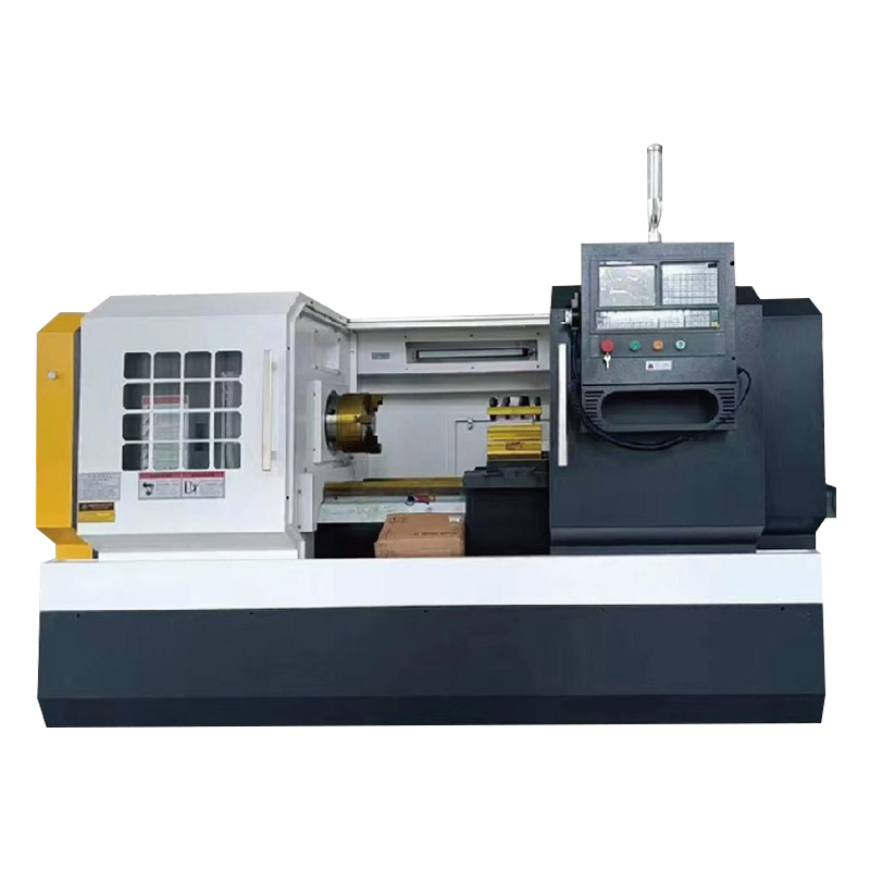
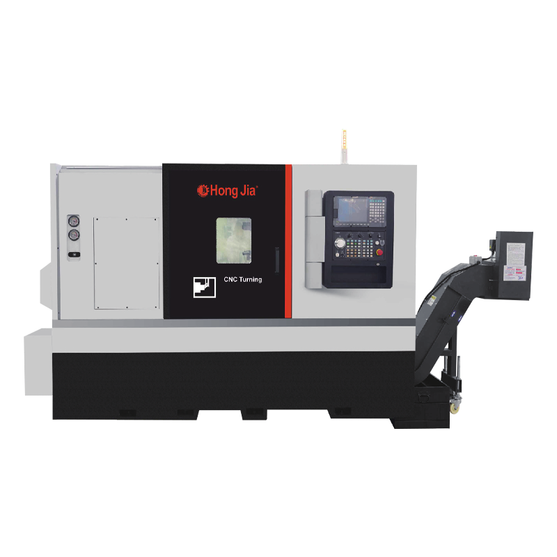
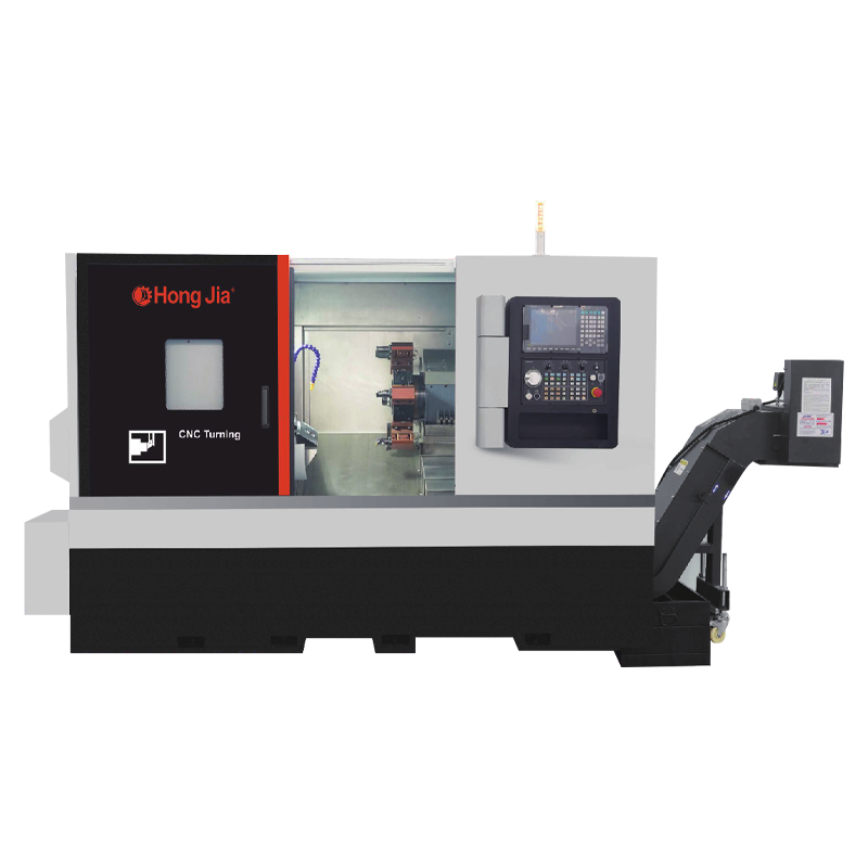
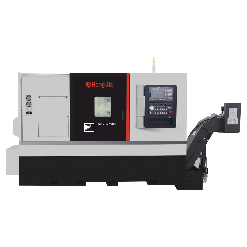
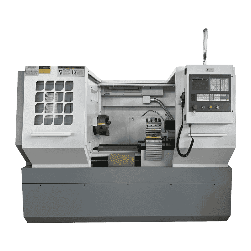 CK6140 High-Precision CNC Horizontal Lathe for Shaft and Disc MachiningThis lathe is ideal for round, symmetric parts like shafts and discs. Its laser-checked axis accuracy and rigid cast bed ensure stable precision, making it a practical choice when turning operations dominate your workflow.View Product →
Mill vs Lathe: Key Differences at a Glance
The table below compares the two machines side by side so the operational contrast is easy to evaluate.
| Comparison Point | Lathe | Milling Machine |
|---|---|---|
| Primary motion | Workpiece rotates | Cutting tool rotates |
| Tool type | Single-point cutting tool | Multi-point rotating cutter |
| Typical part geometry | Round and axisymmetric | Prismatic with flat faces and holes |
| Common operations | Turning, facing, threading, boring, grooving | Face milling, end milling, drilling, tapping, contouring |
| Workholding | Chuck, collet, centers | Machine vice, clamps, fixtures |
| Best suited for | Shafts, bushings, pulleys, flanges, rings | Brackets, housings, molds, manifolds, plates |
Part Geometry: Round Components vs Prismatic Components
If a workpiece has an axis of rotation and can be held in a chuck, it is almost always a lathe job. Motor shafts, drive pulleys, bushings, hydraulic fittings, threaded rods, and valve stems are produced efficiently on CNC lathes and turning centers. The rotating workpiece maintains strong concentricity between all turned diameters, and single-point turning leaves a smooth, consistent surface finish that is difficult to match with any other cutting process.
Milling machines take over when the part consists of flat surfaces, precise hole patterns, slots, angles, or enclosed cavities. Gearbox housings, machine bases, manifold plates, mold inserts, and electronic enclosures are typical milling workpieces. A vertical machining center with an automatic tool changer can mill those features, drill and tap holes, and complete the component in one clamping, which reduces setup time and avoids tolerance accumulation.
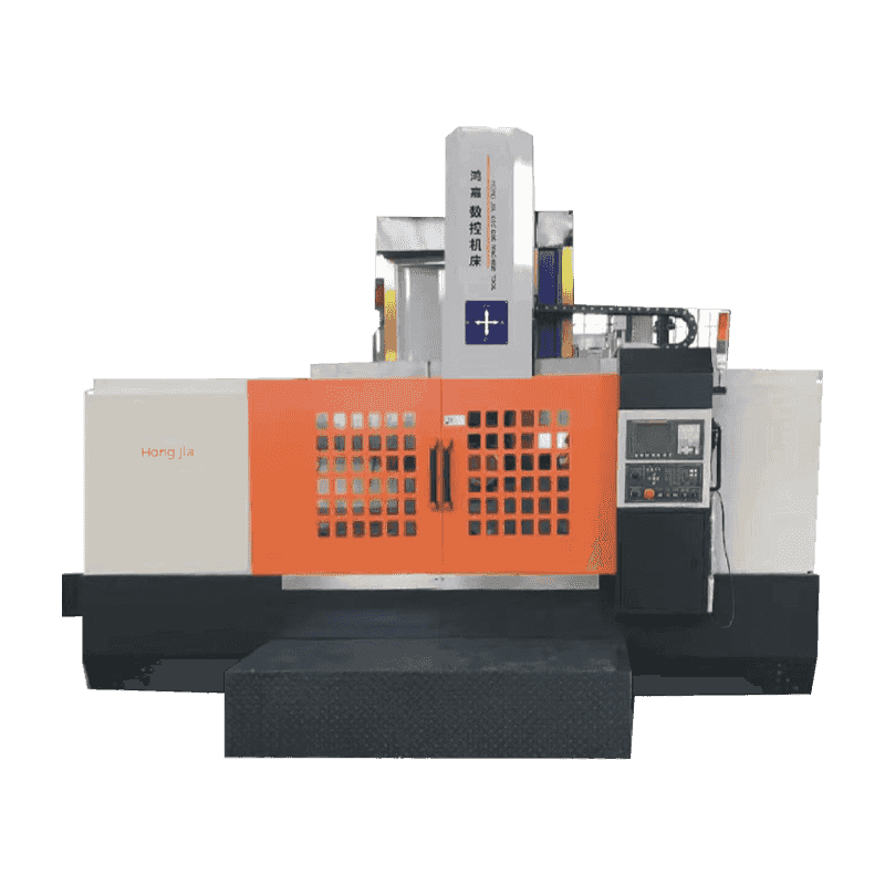
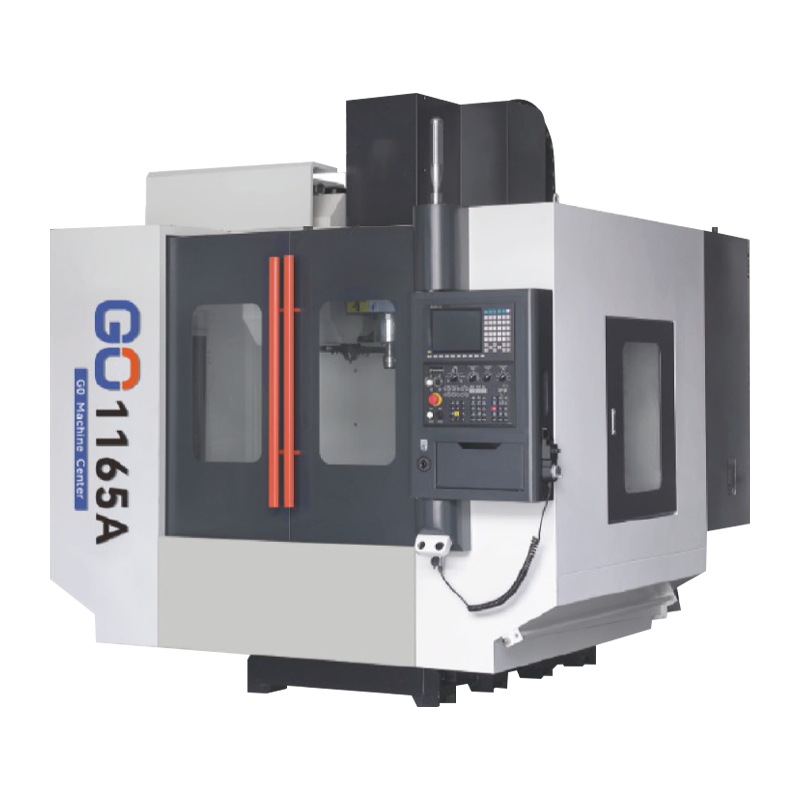 1165A High-Speed Heavy-Duty Vertical Machining CenterFor flat surfaces, hole patterns, slots, and cavities, this machining center offers high speed and precision. Its automatic tool changer and rigid structure support milling, drilling, and tapping in one setup, reducing cycle time.View Product →
Some parts cross the boundary. A shaft with a keyway, for example, is turned first for its diameters and then mounted on a mill for the slot. When this pattern appears in your order mix, owning both machine types becomes the practical solution.
Operations and Practical Production Differences
Each machine type has its own range of standard operations. Knowing these helps you match equipment to the jobs you quote.
Core lathe operations
- Turning — machining the outside diameter of a rotating workpiece along its length
- Facing — producing a flat end surface perpendicular to the spindle axis
- Threading — cutting internal or external threads with a single-point tool
- Boring — enlarging and finishing existing holes using a single-point tool
- Grooving and parting — cutting narrow recesses or separating completed parts from the bar
Core milling operations
- Face milling — generating flat surfaces using the face of a rotating cutter
- End milling — cutting slots, profiles, pockets, and shoulders with the cutter's side edges
- Drilling — producing holes with rotating twist drills, manually or through a tool changer
- Tapping — cutting internal threads with a rotating machine tap
- Contouring — producing two- and three-dimensional profiles through multi-axis feed
Precision behavior differs as well. Lathes excel at roundness and concentricity because every turned diameter is generated from one rotation of the part. Milling machines excel at flatness, squareness, and hole-position accuracy, because those features are referenced from the machine's fixed ways rather than from a rotating spindle axis.
How to Choose Between a Mill and a Lathe
Use the following decision logic in order when planning your equipment list.
- Start with part geometry. A rotationally symmetric part belongs on a lathe; a block, plate, or bracket with machined faces and holes belongs on a mill.
- Identify the critical dimensions. If the main tolerances are on diameters, threads, and faces perpendicular to the centerline, choose a lathe. If they are on flat surfaces, slots, and hole patterns, choose a mill.
- Consider batch size and cycle time. A CNC lathe is very efficient for high-volume turning of round blanks, while a machining center suits batches that combine multiple operations on different faces in one fixture.
- Evaluate secondary operations. If most parts need both turning and milling, plan a two-machine workflow or look at a turn-mill center.
- Check workpiece size and weight. Large-diameter, short parts are often easier to machine on a vertical lathe, while long shafts are better on horizontal turning centers.
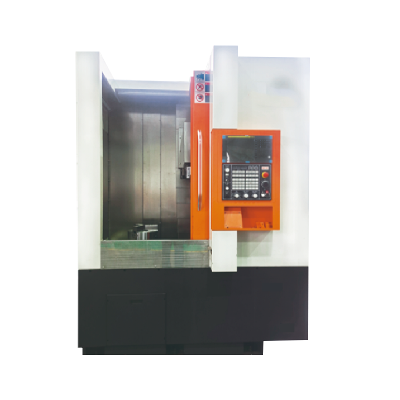
Machine orientation also matters. If your parts are large in diameter and short in length, a vertical lathe can be a smarter choice than a horizontal machine. Our comparison of vertical lathe vs horizontal lathe explains this decision in practical terms.
When You Need Both: Building a Balanced Machine Mix
In practice, a modern machine shop rarely chooses between a mill and a lathe — the most versatile shops install both. A typical workflow sends round blanks to a horizontal turning center for outside and inside diameter turning, then moves the part to a vertical machining center for face milling, drilling, and tapping of mounting features. These two machine types complement each other, and together they allow a shop to quote a much wider range of manufacturing work.
If you are new to the process, review the fundamentals first. Our guide to CNC turning and milling technology outlines the basic operations, machine structures, and workpiece categories behind both processes.
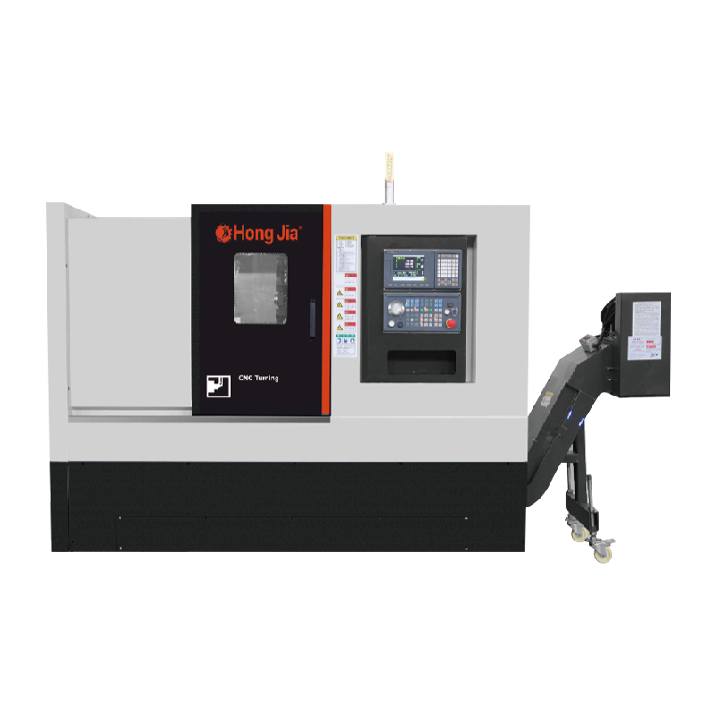
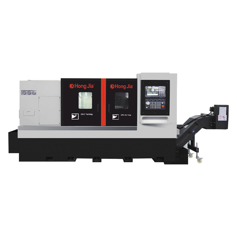
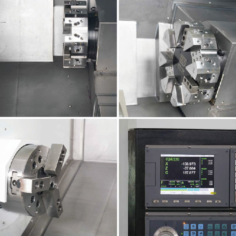 NC-106 Horizontal Turning Center with Milling CapabilitiesThis turning center combines turning with drilling, boring, and milling, reducing workpiece transfers. Its heavy-duty cast bed and servo controls maintain accuracy, making it suitable for complex parts in demanding industries.View Product →
The Bottom Line
The difference between a mill and a lathe comes down to which component provides the cutting motion. When the workpiece rotates and the tool stays relatively fixed, it is a lathe. When the cutter rotates and the workpiece is clamped, it is a mill. Choose according to part geometry first: round and symmetric parts point toward turning; flat, blocky, or hole-dominated parts point toward milling. If your production mix includes both — the common situation in machining — plan for turning centers and machining centers to work side by side, and match each machine's size, power, and configuration to the specific workpieces you need to produce.