
 English
 中文简体
 русский
 Español
 عربى
Don't hesitate to contact when you need us!
 Home / News / Industry News / A Practical Guide to cad and cam: Uses, Selection, and Key Considerations
A Practical Guide to cad and cam: Uses, Selection, and Key Considerations
 2026.11.04
 Industry News
A request for quotation arrives with a STEP file, a PDF drawing, and a delivery date. Before the shop can quote, it has to answer three questions: can the part be held, can the tool reach every feature, and can the machine hold tolerance at the quoted cycle time. CAD and CAM answer those questions in sequence. CAD defines the part; CAM defines the motion that makes it. The handoff between them is where most estimating errors, scrapped first articles, and unexpected tool changes begin.
Content
What CAD and CAM Actually Do
CAD is the geometry side of the workflow. It produces the 2D drawing, the 3D model, the assembly structure, and the dimensions and tolerances that define acceptance. In a job shop, the CAD file may come from the customer, or it may be rebuilt from a drawing because the supplied model is incomplete. CAD answers one question: what is the part?
CAM starts with that geometry but answers a different question: how is the part made? The programmer defines stock, workholding, tool assemblies, operation sequence, cutting parameters, coolant strategy, and toolpath. The output is not a prettier model. It is a machine-specific set of instructions, usually G-code, plus a setup sheet that tells the operator what to load and where to touch off.
| Question | CAD | CAM |
|---|---|---|
| Primary question | What is the part? | How is it made? |
| Core input | Customer drawing, scan, concept | 3D model, stock definition, machine kinematics |
| Core output | 2D drawing, 3D model, bill of materials | Toolpath, NC program, setup sheet |
| Main risk | Missing tolerance or datum | Wrong post-processor, stock allowance, or tool reach |
| Typical owner | Design engineer, drafter | CAM programmer, machinist |
The distinction matters commercially. A design change may cost engineering hours. A CAM change may cost a fixture, a tool, or a prove-out cycle. Treating them as one step hides both costs.
The Handoff: Model Quality Becomes Machine Accuracy
A model can look perfect on screen and still be unusable in CAM. Open surfaces, overlapping solids, mixed units, and missing datums force the programmer to rebuild geometry, and every rebuild introduces a chance to move a feature. For turned parts, the most important handoff is often the axis of rotation and the stock envelope. If the model centerline does not match the spindle axis in CAM, the part will be cut eccentric no matter how carefully the toolpath is generated.
Before programming, check the model against the drawing rather than against the screen:
- Units and scale. Confirm millimetres or inches before import. A 25.4 factor error can survive several operations before it becomes obvious.
- Datum scheme. Agree on the A-B-C datums and make the CAM work offset mirror the drawing.
- Stock condition. Define bar stock, cast blank, or near-net forging; stock changes depth of cut, tool engagement, and cycle time.
- Feature intent. Threads, chamfers, fillets, undercuts, and reliefs need a purpose. A cosmetic chamfer can become a collision on a back-facing tool.
- Tolerance stack. CAD shows nominal geometry. It does not show chucking deflection, thermal growth, or the effect of a dull insert.
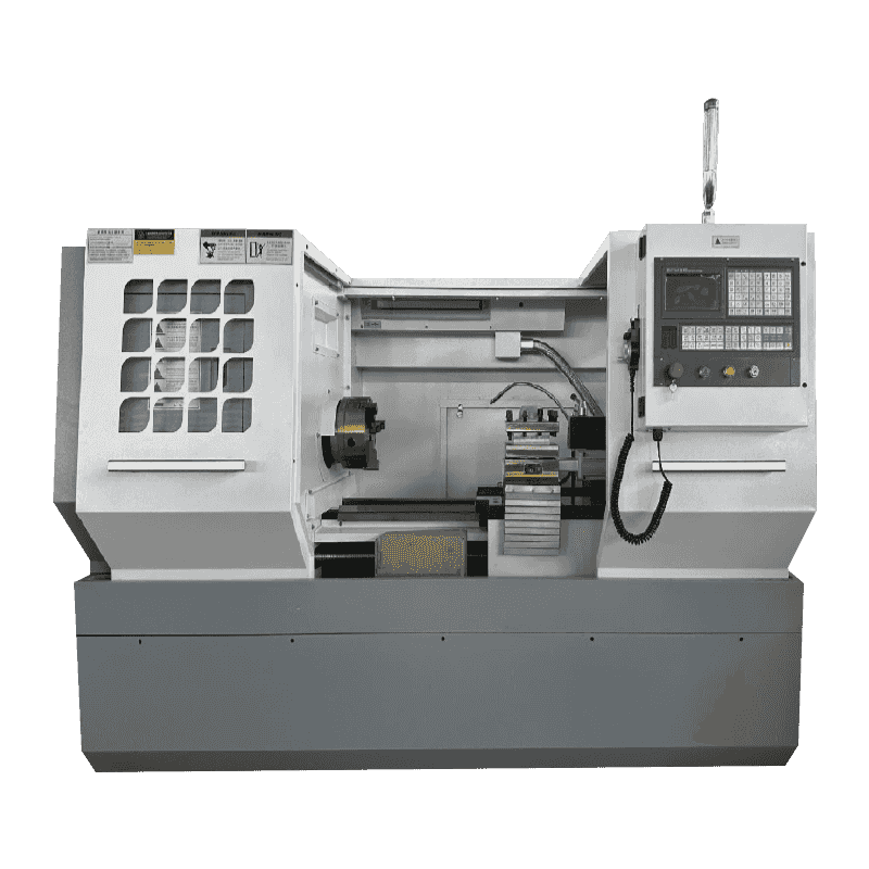
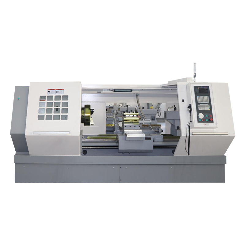
For shops cutting larger bar stock or taking heavy roughing passes, a high-power horizontal lathe with a stable bed gives the programmer room to use realistic depths of cut.
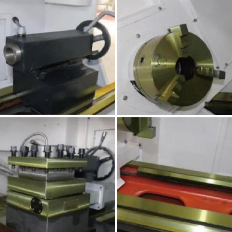 CK6150 High-Power CNC Horizontal LatheHigh-power flat-bed lathe with 82 mm spindle bore and 7.5 kW motor, suited to larger bar stock and heavy roughing with matched CAM.View Product →
From Toolpath to Machine Motion
CAM output is not universal. The post-processor translates a generic toolpath into the code a specific machine expects: tool-change positions, spindle orientation, coolant M-codes, tailstock movement, chuck clamping, bar-feeder handshakes, and subspindle synchronization. A post that is close but not correct can produce a program that looks reasonable on screen and behaves badly at the machine.
Machine features change the programming job more than most buyers expect:
- Axis count. A two-axis lathe and a three-axis turning center with a Y-axis or subspindle require different collision checks and synchronization logic.
- Turret configuration. The number of stations, live tooling, and dual-turret capability determine whether a feature can be finished in one setup or needs a second operation.
- Control capability. Macro support, memory, look-ahead, and canned cycles affect how the program is structured and how fast it can run without dwells.
- Workholding. Chuck, collet, steady rest, and tailstock choices set the stock model and the reachable area.
On a heavy-cutting turning center, the programmer must also respect spindle power and torque. A path that looks efficient in software can stall the spindle or create chatter if the depth of cut exceeds what the machine can absorb.
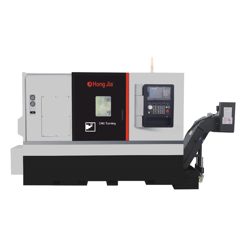
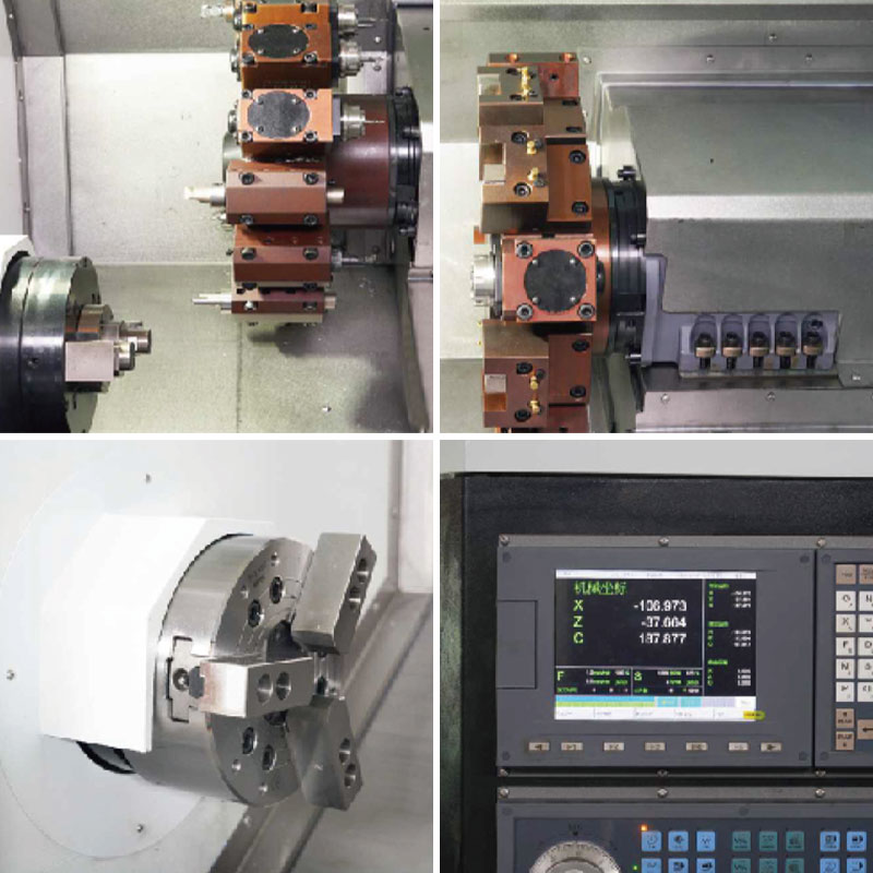 NC-106D Heavy-Cutting Horizontal Turning CenterHeavy-cutting turning center with 56 mm spindle bore, 11 kW spindle, and 12-station power turret, worth reviewing when matching CAM to spindle torque and tooling.View Product →
A Practical Checklist Before You Commit
The cheapest place to catch a CAD/CAM error is still the computer. The second cheapest is a dry run. The most expensive is a scrapped first article on a machine that is already booked.
- Get the native CAD file and a neutral STEP file. Check units, datum, and model integrity before quoting.
- Agree on stock and workholding. Confirm bar size, chuck jaws, fixture clearance, and whether the part needs a tailstock or steady rest.
- Build the CAM setup with the real machine kinematics. Use the actual turret, tool holders, and post-processor, not a generic demonstrator.
- Simulate with stock removal and collision checking. Look for rapid moves through the chuck, tool holder interference, and unreachable features.
- Prove the program and inspect the first article. Verify tool offsets, work offsets, first-cut allowance, and acceptance against the drawing.
This sequence is not paperwork. It is the cheapest way to catch a wrong insert radius, a missing chamfer, or a turret that cannot reach the back face.
Common Misconceptions and Their Cost
CAD/CAM is push-button. CAM still requires decisions about stock, tools, order of operations, and hold points. Software can calculate a path; it cannot decide whether the part will move when the chuck opens.
Any post-processor will work. A generic post can produce code that looks right and runs wrong. Tool-change height, spindle orientation, and coolant sequencing are machine-specific for a reason.
Simulation proves the part. Simulation proves motion, not dynamics. It will not show chatter from a long boring bar or deflection from a weak setup.
The cheapest machine is the cheapest part. If a lower-cost machine adds a second setup, an extra fixture, or a slower cycle, the saving disappears at the quotation stage.
Matching the Machine to the Work
Horizontal lathes and turning centers suit shaft, disc, and sleeve work where the part rotates around a stable centerline. Vertical lathes are often a better fit for large-diameter, short-length parts because workholding is more stable and loading is simpler. Vertical machining centers handle prismatic parts with faces, pockets, and hole patterns. The CAM setup should follow the same logic: choose the machine that removes the most setups without making the part harder to hold.
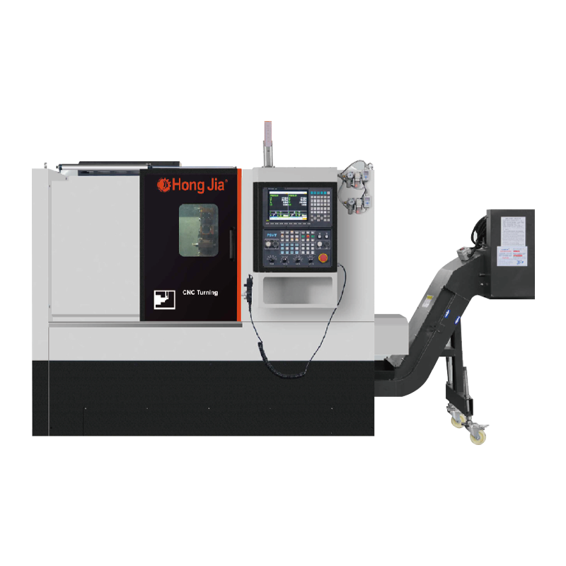
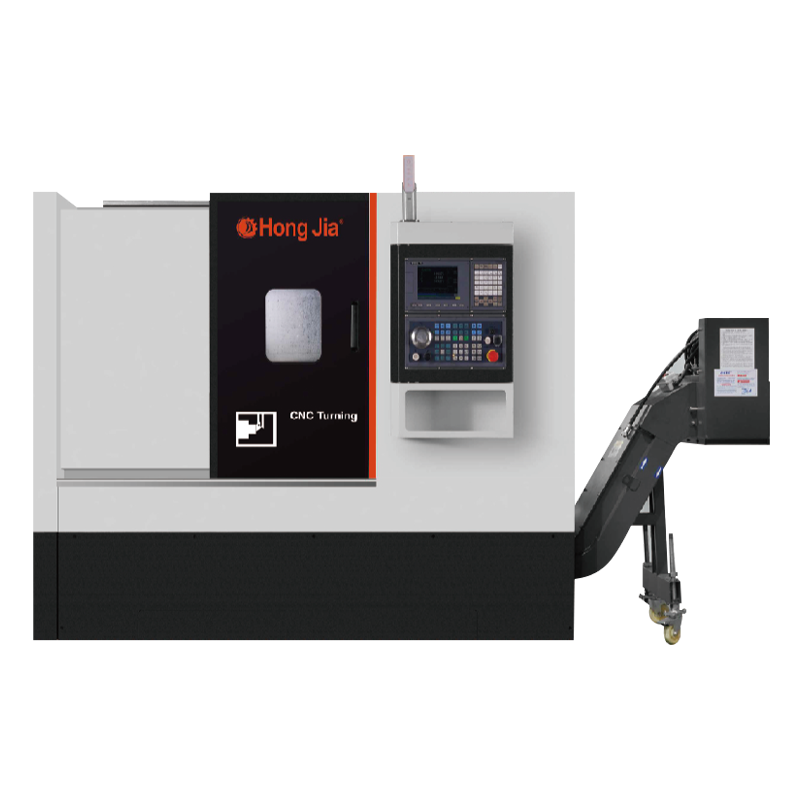
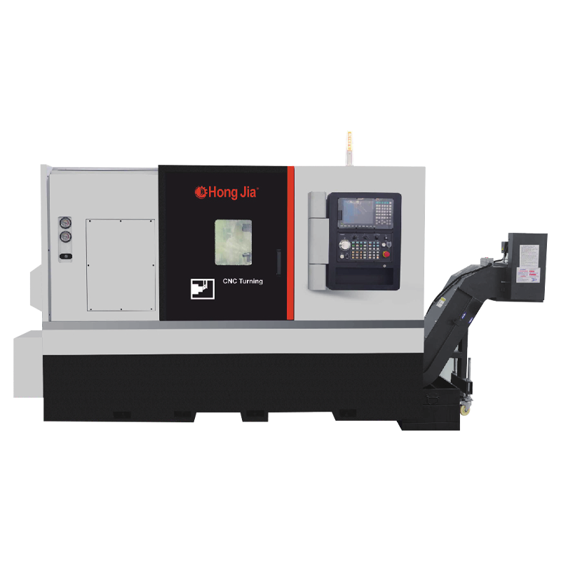
A horizontal CNC turning and milling series typically spans simple two-axis turning through live-tooling and subspindle configurations. That range matters because the same part family may need a basic lathe today and a turning center next year.
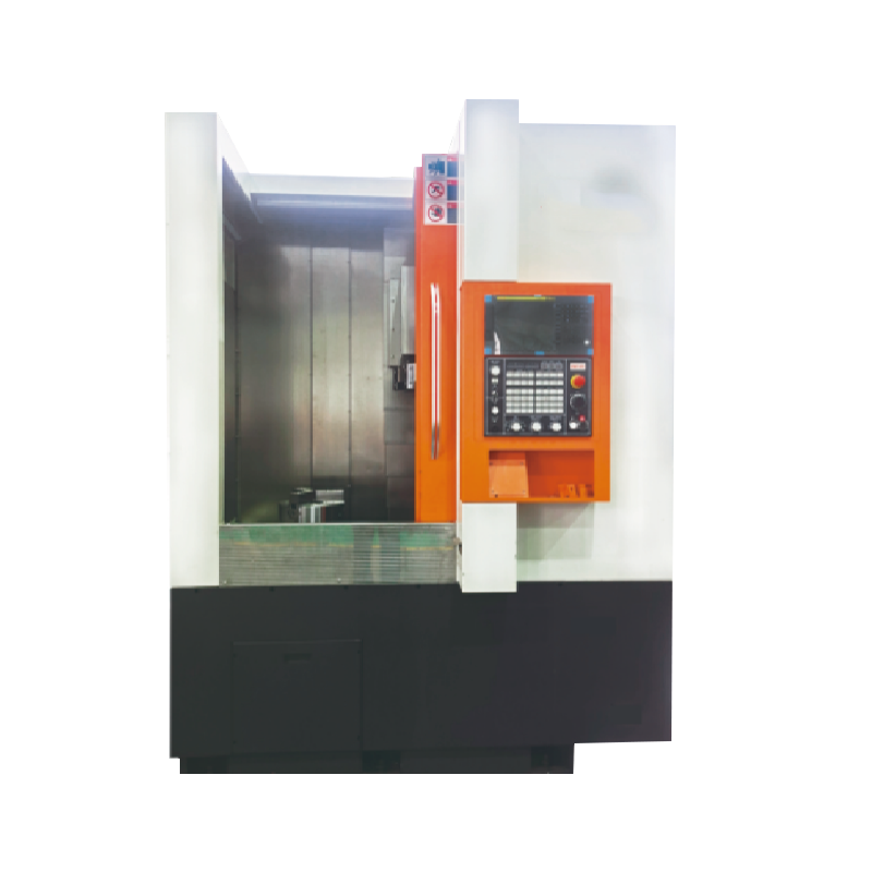
For large rings, flanges, and short shafts, a single-column vertical lathe can simplify workholding and reduce the temptation to overhang the part. The CK5116B CNC single-column vertical lathe is one example of that configuration.
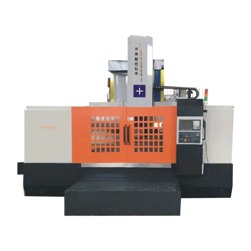 CK-5116B Siemens 808D Single-Column Vertical LatheSingle-column vertical lathe with 1400 mm hydraulic chuck and 1600 mm max tool post diameter, useful for large rings and flanges where workholding simplicity matters.View Product →
CAD and CAM are not software categories to compare on a feature list. They are the handoff between a drawing and a cut part. Get the model clean, define the stock and workholding honestly, post to the actual machine, and treat the first article as a test rather than as production. Done that way, the machine becomes a predictable part of the quote instead of the variable that decides whether the job makes money.
