
 English
 中文简体
 русский
 Español
 عربى
Don't hesitate to contact when you need us!
 Home / News / Industry News / Five-Axis CNC Machining: How It Works, What It Costs, and When It Pays Off
Five-Axis CNC Machining: How It Works, What It Costs, and When It Pays Off
 2026.11.18
 Industry News
A hydraulic manifold with twelve cross-drilled holes at compound angles lands on the desk for quotation. On a three-axis mill it needs five setups and five fixtures, and the third setup alone introduces a locating error of roughly 0.03 mm that every later operation has to live with. On a five-axis machine the same part runs in one clamping.
That comparison is the entire business case. Five-axis CNC does not win work because it looks advanced; it wins because it deletes setups, and deleting a setup deletes a fixture, a re-clamp, an operator judgement and a layer of tolerance stack that nobody can control afterwards. If a part family on your floor still needs four or more setups, five-axis is worth modelling seriously. If it needs one, the capital is usually better spent on capacity you will use every day.
Content
What Five-Axis CNC Actually Means
Five-axis CNC is not one machine type. It describes any machining centre that can position or drive the cutting tool along three linear axes — X, Y and Z — plus two rotary axes chosen from A (rotation about X), B (rotation about Y) and C (rotation about Z). The axis count matters far less than the mode of operation: positional or simultaneous.
3+2 positional machining
The two rotary axes index to an angle and clamp. Cutting then happens exactly as it would on a three-axis machine, only from a different direction. The rotary axes behave like fixtures made of metal: orientation changes take seconds, and a locked rotary joint is close to a solid casting in stiffness. For most job-shop work — brackets, housings, plates with angled faces — 3+2 delivers the bulk of the benefit at a fraction of the programming effort.
Simultaneous five-axis machining
All five axes interpolate together so the tool axis follows the surface. This is what impellers, blisks, blades, implants and deep contoured mould cavities require, and it is also the mode that makes undercut and cross-hole features reachable without re-fixturing. It demands CAM with machine simulation, a post-processor proven on scrap, and operators who understand rotary limits and singularities.
| Configuration | How the machine behaves | Typical use | Programming effort | Rigidity |
|---|---|---|---|---|
| 3-axis | Fixed spindle; part repositioned manually between setups | Prismatic parts with features on two or three faces | Low | Highest |
| 3+2 positional | Rotary axes index and clamp; cutting stays in a fixed orientation | Angled faces, cross holes, five-face work in one clamping | Moderate | High when clamped |
| Simultaneous 5-axis | All axes interpolate while the tool is in cut | Impellers, blades, contoured moulds, undercut features | High — simulation and a verified post required | Lowest, especially with rotary mass in the head |
The Three Machine Builds and What They Do to Your Setup
Where the rotary axes physically sit changes rigidity, work envelope and the weight of part you can hold. Three layouts cover almost everything on the market.
- Head/head: both rotary axes live in the spindle head, so the table stays flat and can carry heavy or awkward parts. The penalty is moving mass high in the structure, which limits size and stiffness — most common on smaller machines.
- Head/table: one rotary axis in the spindle, usually B, and one in the table, usually C. This is the most common compromise: usable rigidity, a practical envelope and good access for mid-sized work.
- Table/table (trunnion): both axes sit in the table, tilting and rotating the workpiece. Very accurate and rigid for parts that fit, but the trunnion caps part weight, and gravity acting on a heavy workpiece shows up as positioning error on the rotary encoders.
Check rotary torque ratings against the part you actually intend to run. A table rated at 200 kg static holding capacity may be rated at a third of that once the axis has to accelerate the load, and the dynamic figure is the one that survives contact with a cycle time.
Where the Money Comes Back
Five-axis payback rarely appears as a faster cycle. It appears as hours removed from the front and back of the cycle, and as defects that stop happening.
Setup elimination
A four-setup part that becomes a one-setup part removes three fixture designs, three proving runs and three chances to load the workpiece the wrong way round. Where a setup costs 45 to 90 minutes of spindle-idle time, that line item alone often carries the case.
Shorter, stiffer tools
Deep cavities on a three-axis machine force long tools, and deflection rises with the cube of overhang. Tilting the head lets you reach the same feature with a tool 30 to 40 percent shorter, which can multiply stiffness several times over. The visible result is a better surface finish and longer tool life; the hidden result is fewer semi-finish passes.
One datum instead of a stack of them
Three setups each contributing 0.02 mm of location error do not deliver 0.02 mm overall — worst case they deliver roughly 0.06 mm, and it usually surfaces as a positional callout between two features machined in different setups. A single clamping collapses that stack to one contribution. Rigidity at the source matters just as much, which is why the same reasoning sits behind high-rigidity horizontal turning centers.
Tool axis control on contoured surfaces
With the tool axis held near the surface normal, a ball-nose cutter keeps working around its effective diameter instead of dragging at the near-zero cutting speed at the tool tip. Stepover can be widened slightly, and manual polishing time drops in a way that never shows up in a CAM estimate.
The Costs That Rarely Appear in the Quotation
The machine price is the least surprising number in the project. The rest tends to arrive afterwards, in invoices and in hours.
- CAM and a verified post-processor. A simultaneous five-axis post is machine-specific and has to be proven on scrap before it touches a customer part. Budget for simulation software as a requirement, not an option.
- Programming hours. A first simultaneous toolpath can take three to ten times as long to program as an equivalent three-axis job. Keep roughly 80 percent of the workload in 3+2 and reserve simultaneous paths for features that genuinely need them.
- Operator skill. Rotary limits, singularities, collision awareness and in-process probing are not absorbed in a week, and a trunnion crash is an expensive way to learn them.
- Tool holders and clearance. Short, well-balanced holders, more of them in the magazine, and enough clearance to keep the head out of the fixture at every angle.
- Building and services. Foundation work, coolant and chip management, and a stable ambient temperature if the rotary encoders are expected to hold accuracy across a full shift.
- Maintenance and calibration. Rotary backlash, encoder checks and geometry verification belong in the annual plan from day one, not after the first out-of-tolerance batch.
A Practical Test Before You Commit
Run this against three months of job cards, not against the brochure.
- Count the parts that need more than two orientations. If that group is under a fifth of your workload, 3+2 on an existing vertical machine may already cover it.
- List the tolerances you currently fight. If the problem is a location callout between features on different faces, five-axis fixes it. If it is a size tolerance on a single face, it does not.
- Model payback on setup hours and rework rather than cycle time. Cutting time on a five-axis machine is often no better than on a three-axis machine, and quoting it as a speed gain flatters the numbers.
- Price the alternative honestly: extra in-house setups versus subcontracting the family to a five-axis shop. At low volume the subcontractor usually wins, and no capital is tied up.
If Your Shop Is Built Around Turning
Not every setup problem needs a five-axis milling machine. On shaft-type and chuck-type parts, the first real gain usually comes from finishing more operations in one clamping on a lathe — the same setup-elimination logic, applied to a different spindle orientation.
Three-axis synchronous turning, with a C axis, live tooling and a synchronised second spindle, lets a shaft be machined from both ends against one datum, with milled flats and cross holes finished in the same cycle. That removes the second operation, the second fixture and the second chance to lose concentricity.
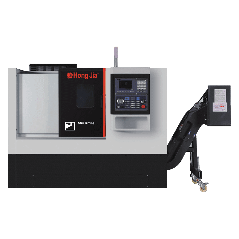
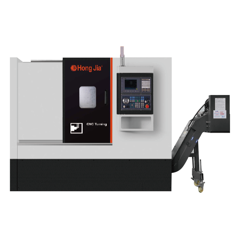
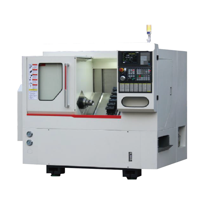
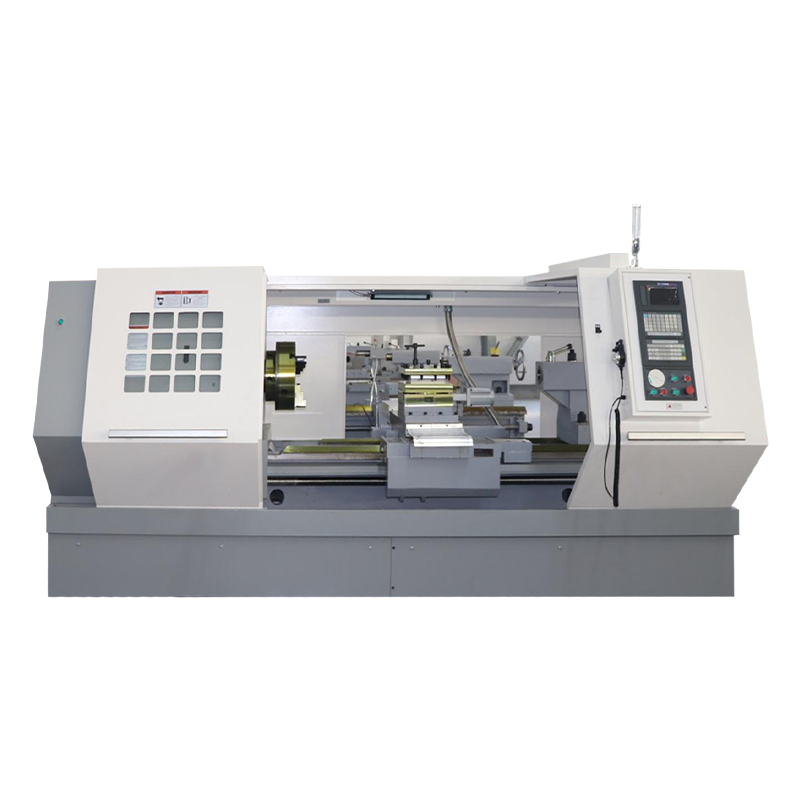
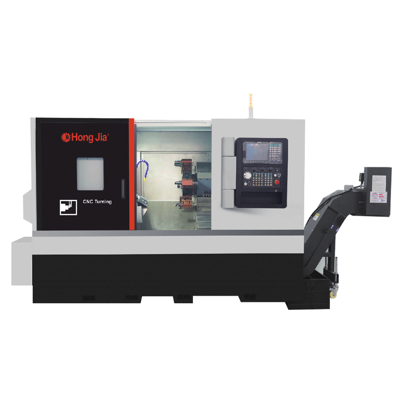
 NC-106D-Y 3-Axis Synchronous Horizontal Turning CenterA three-axis synchronous turning centre with driven turret and Y axis, suited to completing turning, milling, drilling and boring on shafts in fewer setups.View Product →
Where a part needs turning, drilling and boring in a single hit, a turning centre with a driven turret and boring capability compresses three operations into one. The economics are identical to five-axis work: the saving sits in fixtures, not in spindle speed.
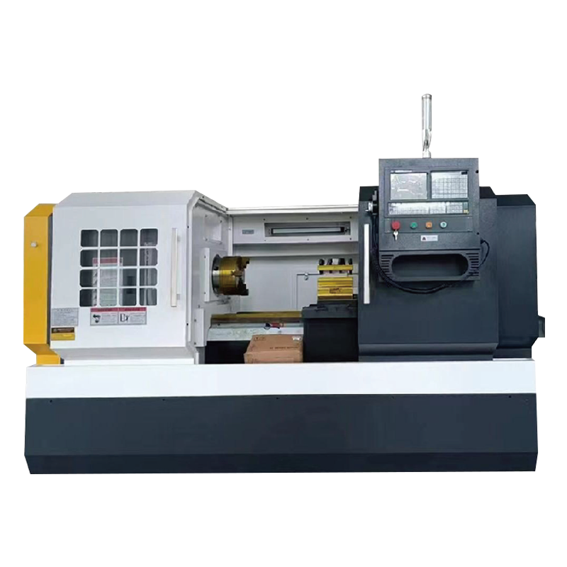
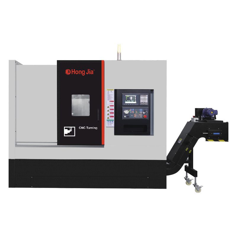
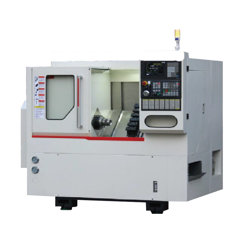 T36P Turning, Drilling and Boring Horizontal Turning CenterA horizontal turning centre for turning, drilling and boring of complex workpieces, with high-rigidity structure and a 75 L withdrawable coolant tank.View Product →
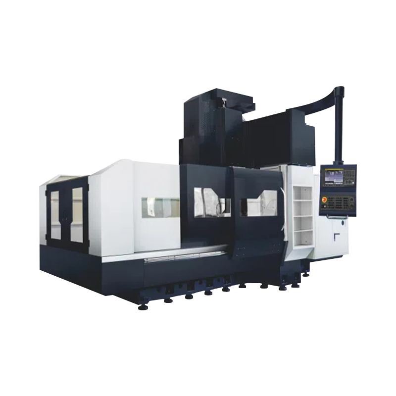
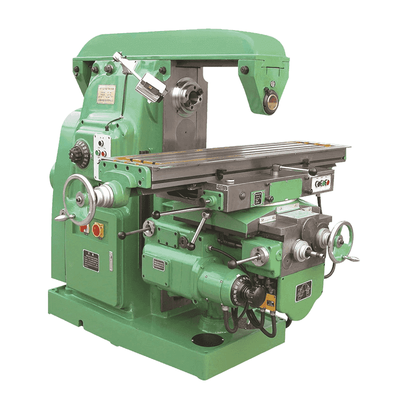
For large prismatic work, a double-column machining centre provides a work envelope a C-frame cannot, and with an indexing head it covers angled faces in 3+2 without paying for full simultaneous control.
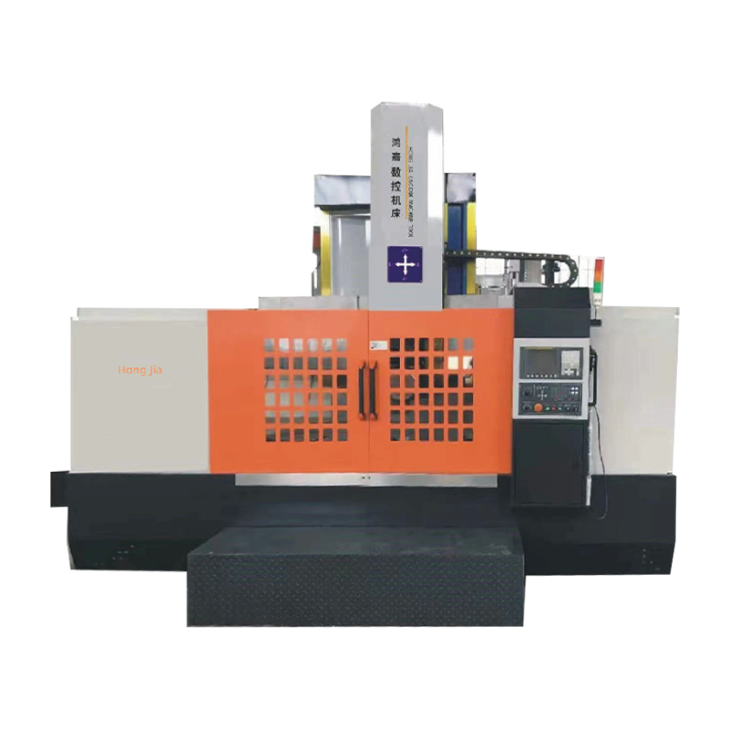
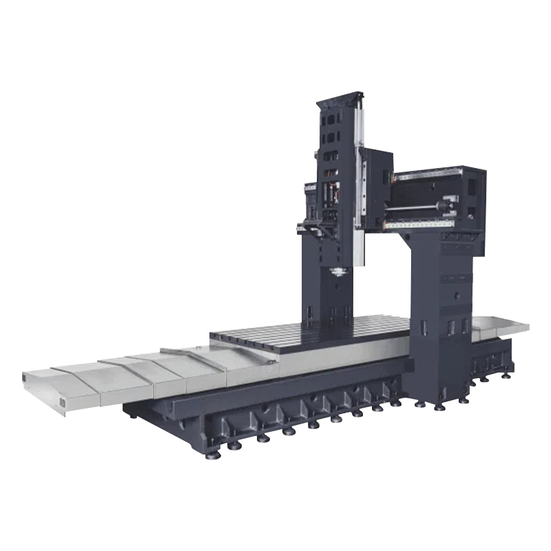 Double Column Machining Centre for Large WorkpiecesA double-column machining centre series for large, heavy workpieces, with high-strength cast iron bed, gantry widths to 1400 mm and rapid traverse to 20 m/min.View Product →
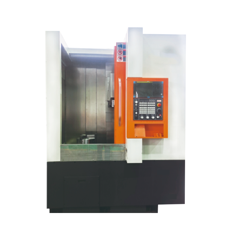
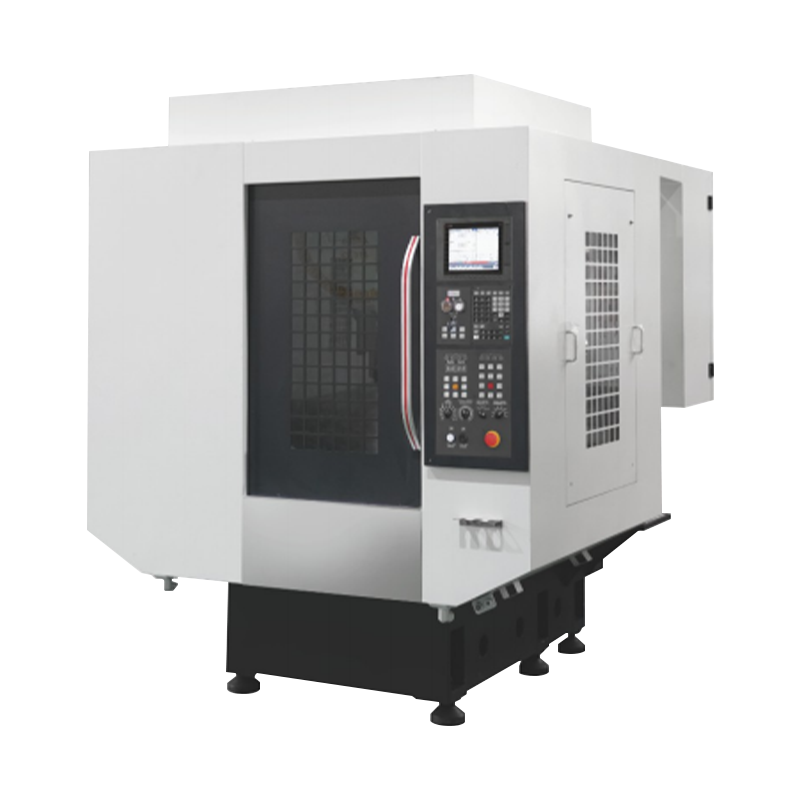
The catalogue behind this site sits at that earlier stage of the same logic — horizontal turning centres, vertical lathes and machining centres built around reducing how many times a part is clamped; the company background sets out the production base behind it. If a part family genuinely needs simultaneous five-axis, that capability has to come from a machine designed for it. What a turning centre or a 3+2 machining centre can do is remove the setups that never needed five axes in the first place.
Getting the Floor Ready
The machine arrives long before the process is stable. These items decide whether the first month is productive or painful.
- Foundation and levelling: follow the load and anchor requirements, then re-check level after the first weeks of cutting.
- Thermal stability: rotary encoders and spindle growth both respond to temperature swings; a workshop that varies by ten degrees across a shift will show it in the parts.
- Probing and tool data: in-machine probing converts a five-axis machine from a fast cutter into a self-correcting one, and it is the cheapest insurance against fixture error.
- Verification: a ballbar check and a test cut on a known artifact, including rotary centre offsets, before any customer work is released.
- Dry runs: prove each new program in simulation, then in air with the door closed, then in aluminium before it goes anywhere near a deliverable.
Five-axis CNC is a setup-elimination tool with a high entry ticket. Buy it when the part family has compound angles, cross features or a tolerance stack that three setups cannot hold — and buy it with the CAM, the post-processor and the training already budgeted, because those are what convert axis count into shipped parts. If the honest answer is that two or three part numbers need simultaneous control while the rest run happily in 3+2, subcontract those few and spend the capital on capacity you will load every week.
