 English
 中文简体
中文简体 русский
 Español
 عربى
عربى


Don't hesitate to contact when you need us!
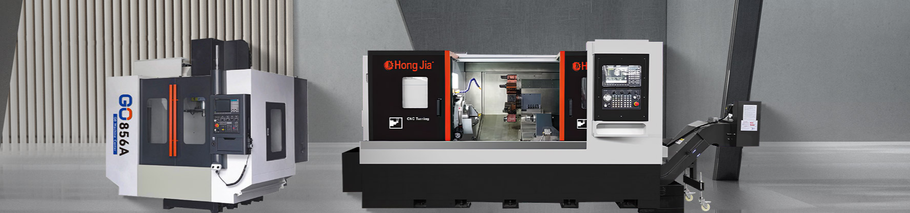
What is a horizontal turning center?
 2025.09.11
 Industry News
Horizontal turning centers excel at traditional turning operations and also integrate multiple machining functions, including drilling, boring, milling, and tapping. A single machine can perform multiple operations, significantly reducing workpiece transfers and improving production efficiency. Horizontal turning centers undergo rigorous heat treatment to ensure they maintain stability and precision even under long-term, heavy-duty machining, providing users with greater reliability and a longer service life. Horizontal turning centers are widely used in aerospace, automotive, mold manufacturing, precision machinery, and other fields.
1. Features of a horizontal turning center
Horizontal structure: The spindle is arranged horizontally (the workpiece rotates horizontally), in contrast to vertical turning centers (where the spindle is vertical). This layout is more suitable for machining long shafts and heavy workpieces, avoiding deformation caused by gravity.
Multi-processing capabilities: It integrates turning, milling, drilling, tapping, and other functions, and uses multi-axis linkage and live tooling to complete multiple machining operations in a single clamping.
High-rigidity structure: Utilizing large-size guideways and high-quality castings, it is suitable for high-volume machining.
Multi-axis control: The typical configuration is X and Z axes (turning) + Y axis (milling) + C axis (spindle indexing), with some models also equipped with a B axis (milling cutter tilting).
Live tooling: The spindle can be equipped with rotating tools (such as milling cutters), enabling side or end machining without secondary clamping.
Automatic tool changing system: Equipped with a tool magazine (disc or chain type), it supports the rapid changeover of dozens of tools. Compatible with large-diameter workpieces: Eliminating the constraints of a vertical gantry structure, this machine is suitable for machining large flanges and discs.
Reduced clamping errors: Complete machining with a single positioning operation, achieving IT5 (μm-level) accuracy.
Improved efficiency: Saving over 50% of machining time compared to traditional lathe and milling machine processing.
Complex process integration: Operations such as thread milling and eccentric drilling, difficult to perform on traditional lathes, are possible.
2. Typical Applications
Aerospace: High-precision turning and milling of engine rotors and turbine discs.
Energy equipment: Nuclear power main pump casings and steam turbine shaft components.
Automotive: Integrated machining of transmission output shafts and brake drums.
Mold manufacturing: Precision turning and surface milling of large injection mold cores.
3.Common faults of horizontal turning centers
(1) Abnormal vibration/heating of the spindle
Causes: bearing wear (common in angular contact bearings), main shaft dynamic balance failure, insufficient lubrication (dry grease or blocked oil path), uneven belt tension.
Performance: Vibration traces appear on the processed surface, and the temperature rise of the spindle exceeds 60℃.
Treatment: Use a dial gauge to detect the radial runout of the main shaft (standard value ≤0.005mm); use temperature difference method to install the bearings (heat to 80-100℃); check the pressure of the oil-air lubrication system (usually 0.2-0.5MPa).
(2) The guide rail is worn or crawling
Reason: The seal failure of the protective cover leads to chip intrusion, poor lubrication, and excessive pre-tightening force of the guide rail.
Performance: Moving axis trembles, positioning accuracy is too poor (such as repeated positioning error of X-axis>0.01mm).
Treatment: Apply special guide rail oil after cleaning the guide rail; adjust the insert gap (0.02mm is better if the feeler gauge detects no entry).
(3) Servo driver alarm
Causes: Motor overload, encoder cable interference, power supply module abnormality.
Processing steps: Check the motor insulation resistance (>1MΩ); replace the shielded twisted pair encoder wire (impedance needs to be matched); measure the balance of three-phase input voltages (deviation <5%).
(4) Failure to change tools in the tool magazine
Typical failure:
Robot stuck knife: The handle is worn out by pulling nails (the contact area of the conical surface is less than 80% and needs to be replaced);
Tool numbers are confused: The tool sleeve encoder is contaminated or the counting switch is invalid.
Emergency plan: Reset the origin of the tool magazine in manual mode (refer to the machine tool maintenance manual).
